
Blog
Design In Reinforced Concrete Constructions

When people started using stone as a building material centuries ago, they were limited in practice because they did not have a good binding material. The low tensile strength of the stone also prevented passing large openings. The desire to cross large openings has prompted people to look for alternative systems and arch systems have been developed in which the cross section works with pressure as a whole.
Arch System
The desire of the people to achieve the never-ending better resulted in the invention of binders such as natural cement and lime, which were thought to be used by the Romans for the first time. More durable structures could be built with these binding materials. The cement commonly used today was found by an English mason named John Aspdin. Aspdin, while patenting the cement, registered it as “Portland Cement” because it resembles the stones found in Portland.
Portland Stone
It was determined that the concrete, which was produced by mixing cement by mixing sand, gravel and water, was not resistant to impact effects and pulling, and it was strengthened with steel bars and the resulting material was named reinforced concrete.The basic points in reinforced concrete, which is a more flexible composite material that can resist both tensile and pressure by the addition of steel bars to concrete, are stated below.
- All pulling is covered by steel bars.
- The cooperation of steel and concrete is provided by the interlocking and adherence between these two materials.
- Expansion coefficients of concrete and steel are very close to each other.
Designing the Load Bearing System
According to the results of the earthquakes that caused severe damage in our country, which has a large reinforced concrete structure stock, the main conditions in earthquake resistant building design are;
- Architecture designed to be resistant to earthquakes: Designs that do not contain unwanted irregularities in the building (torsion, short column effect, etc.)
- Compliance with regulations and specifications: Design in accordance with the issues specified in TBDY2018 and TS500.
- Qualified material, compliance with the project on site and inspection: Proper application and maintenance of concrete in the field; The compliance of the number and size of the reinforcement to the project is to ensure that the reinforcement is properly clamped.
Even if the regulations and specifications specify certain limits and calculation methods, the arrangement of the load bearing system belongs to the engineer making the design. The building to be designed as reinforced concrete; It is of great importance to have a regular load bearing system suitable for the purpose of use, the seismicity and ground condition of the area where it will be built. The behavior of a structure whose load bearing system is well calculated but has an irregular and unsuitable load bearing system; The load-bearing system is more and more negative than the behavior of a roughly calculated structure, but with a fairly regular and suitable bearing system. Therefore, structural system decisions are very important in earthquake resistant building design.Basic points to be considered while making load bearing system decisions;
* The structure must have sufficient rigidity: Under the effects of earthquakes, the structure oscillates and converts some of the earthquake energy into motion energy. However, horizontal displacements should not exceed certain limits in these oscillations, and lateral displacements should not be permanent in light and medium earthquakes.
* The necessary strength should be provided in the structure: The earthquake-induced section effects on the carrier elements should be determined and strength should be provided by making the necessary dimensioning.
* The structure should be designed as ductile: Ductility; material, cross-section, load bearing system element and the ability of the structure to make deformation without a significant decrease in the bearing strength. Thanks to the ductility, sudden collapses do not occur in the structure.
In order to provide ductility in reinforced concrete structures, some basic issues should be considered;
1) Limiting the ratio of reinforcement: In slabs and beams; Ductility can be achieved by limiting the amount of tensile reinforcement in the cross-section and allowing the reinforcement to reach flow before the concrete breaks under pressure.
2) The use of stirrups and crossties: It prevents sudden and brittle collapse of the carrier elements due to the shear force before the bending reinforcement flows.
3) Strong column-weak beam: The sudden collapse mechanism is prevented by designing the plastic hinges to occur primarily in the beams.
4) The use of tight stirrups at column-beam joints: The strength and ductility of the junction area should be increased by tightening the stirrups in the beam and column sections in the column-beam joints that are expected to have the most difficulty in the earthquake.
5) Adequate adherence and ensuring sufficient clamping: One of the factors that reduce ductility in the bearing structure elements is the shear force effect and the other is the weakening of adherence. Failure to provide sufficient adherence reduces the internal forces that meet the shear force. Ensuring adherence can be provided by sufficient clamping length and having tight stirrups along this distance.
* Structural irregularities should be avoided:
Irregularities in the Plan:
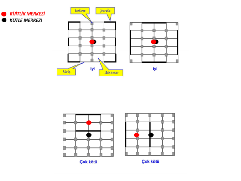
a)Torsion Irregularity (A1): It is the case where the ratio of the largest relative storey displacement at any floor to the average relative story displacement in the same direction at that floor for any of the two specified earthquake directions is more than 1.2.
“The center of rigidity and the center of mass of the building should be designed as close as possible to prevent A1 irregularity.”
b) Discontinuity Irregularity in Floors (A2): The total of void areas on any floor is more than 1/3 of the total floor area. This irregularity should not be included in the design, as this prevents the earthquake loads to be transferred safely to the vertical bearing elements.
c) Irregularity of Protrusions in the Plan (A3): It is the case that both the dimensions of the protruding parts in the floor plans in two directions perpendicular to each other are greater than 20% of the total plan dimensions of that floor in the same directions.
Vertical Irregularities
- Strength Irregularity Between Neighboring Stories (Weak Stories) (B1): In reinforced concrete buildings, in either of two earthquake directions perpendicular to each other, the total effective shear area on any floor is the effective shear area of the upper storey (effective shear area = shear wall area + column area + 0.15 x wall area) ratio is less than 0.8.
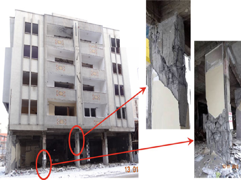
Weak Story
- Stiffness Irregularity Between Neighboring Stories (Soft Storey) (B2): For any of the two earthquake directions perpendicular to each other, the ratio of the storey drift ratio in any storey to the relative storey drift of the upper or lower storey is more than 2.0.

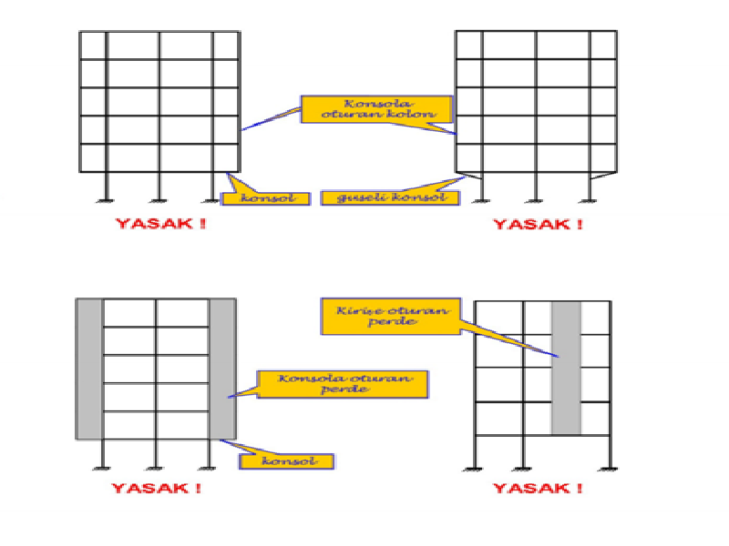
- Irregularity of the Vertical Elements of the Structural System (B3): It is the situation where the columns or curtains are lifted on some floors and placed on the beams or gusset columns or the curtains on the upper floors are placed on the columns at the bottom.
(The design of reinforced concrete structures is a more comprehensive and deep topic. We have tried to specify the basic principles in this article.)
As İntac engineering, we have successfully completed many reinforced concrete projects.
Latest Blog
-

-

Methods Used In Earthquake Performance Analysis
4 July 2024 -

Reinforced Concrete Calculation Static Report
31 January 2024 -

Steel Calculation Static Report
31 January 2024 -
What Is CFD Analysis?
22 December 2023 -

What Are The Benefits Of CFD Analysis?
22 December 2023 -

Silo Reinforcement with Post-Tensioning Method
26 September 2023 -

Post Tensioning Method in Cantilever Slabs
4 September 2023 -

Post-Tensioning Application In Reinforced Concrete Silos
22 August 2023 -

Components Of Post Tensining
16 August 2023 -
What Are Pre-Stressing And Post-Tensioning?
11 August 2023 -
What is Prestressing?
8 August 2023 -

History Of Post Tensioning
8 July 2023 -

-

Post Tensioning Method In Foundations
14 June 2023